The Shuffler is a digital loop pedal with the ability to shuffle the loop by breaking it into even slices and rearranging them randomly. This can create many musical variations from a single loop. The user has the ability to shuffle as many times as is needed and overdub on top of the shuffled loop.
A typical loop pedal has the following interfaces:
- Audio in
- Audio Out
- Record/Overdub switch
- Play/stop switch
- Reset control
- Output volume
Often, in existing loop pedals, some controls are combined into a single switch, for example, the reset control would be done by holding down one of the switches for a few seconds rather than just pressing it. I gave this control it’s own switch to simplify prototyping and testing.
This design has one additional switch to implement it’s unique feature: Shuffling.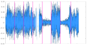
The image above is the waveform of some test audio from MATLAB. I implemented the shuffling algorithm within MATLAB to verify that it worked before moving to an embedded solution. The pink lines show where the audio was sliced. The waveform shows the audio after the slices were rearranged.
This originally worked by copying sections of a recorded audio file and then writing them to a new audio file in a different order. When I implemented this on the Teensy 3.1 microcontroller platform it proved to be too slow for live use.
The solution that allowed instant shuffling was to save memory locations that evenly divided the file, and than jump to a new memory location to play form within the file after a complete slice had played.
I stored the memory locations in an array, and this array would be shuffled once when the shuffle button was pressed. By doing this, the same pattern would be played every loop, and the arrangement would only change when the shuffle button was pressed.
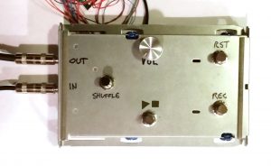
Above is the functional prototype of the pedal. This uses 4 foot switches and one knob for volume.
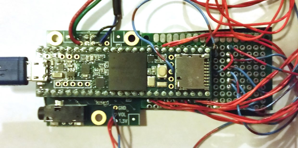
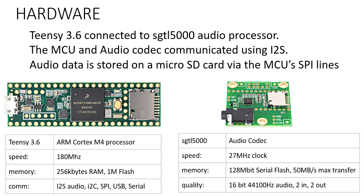
The hardware platform used was a Teensy 3.6 with an audio codec daughter board. The audio codec handled all of the digital to analog conversion and connected to the audio input and output lines. Digital audio data is sent between the microcontroller and codec for advanced processing and storage.
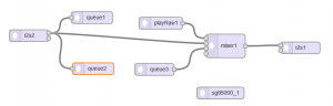
The diagram below shows the flow of audio between the codec and microcontroller.
i2s2 is the digital connection that carries the input audio data, and i2s1 is the audio output.
Overall hardware block diagram: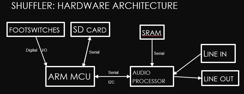
The code on the microcontroller runs a loop that is precisely timed to receive the input buffer and send out the modified buffer. This is extremely critical during overdubbing.
While overdubbing, the audio is played from the file to the codec, the codec adds the incoming signal to this audio using a virtual mixer, and the resultant signal is sent to the output, and saved to the file at the location audio was just played from. The diagram below shows this process, with the audio slice shown in orange.
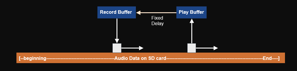
The audio is written to the file a fixed number of samples behind the audio that is being read and played. This has to be done because of the delay in processing time. If this was not done, the audio that was overdubbed would be shifted from where the musician thought it was recorded at.
One of the major problems was noise during overdubbing. When the microcontroller wrote to the SD card, crosstalk would be picked up on the audio lines from the serial lines and recorded to the file.
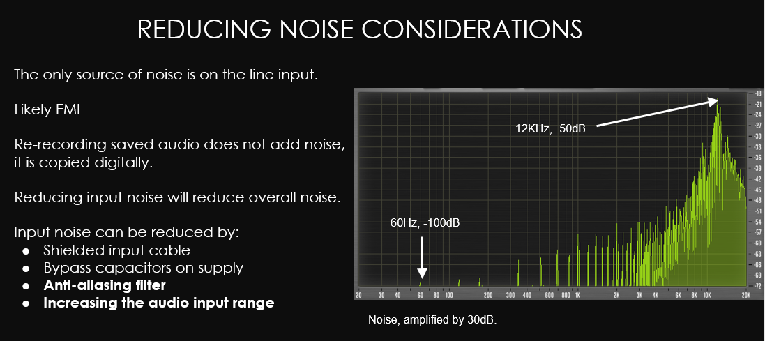
I discovered that this was caused by a coding error. The device would read incoming audio continuously from the file, and it could read this faster than the audio could be played. The first clue to this was that the noise was harmonic, rather than white noise. The noise only existed at certain frequencies. I thought at first it was AC hum, but then the 60Hz signal should have been much higher than the higher frequencies. The high frequencies actually correlated to the frequency of the serial lines and the aliasing that resulted when sampled at 44,100 Hz.
I corrected this by having only one sample read and not read another sample until the previous one had finished playing. This meant that the audio was read from the SD card in very short bursts so the serial line was active less than 1% of the time, instead of continuously. Now the noise was no longer being picked up by the input audio line.
The final design actually proved to work very well, but shuffling required the musician to count very accurately. By default the device shuffled into 8 slices, so it worked best with music in even time signatures, such as 4/4 or 4/8. 3/4 time signatures, triplets, and syncopation did not work well with shuffling since the loop was sliced on what mathematically should have been the beat.
To improve the design in a future version I would add an adjustable number of slices, and possibly consider adding a beat detection algorithm, which would be a project on it’s own.