Senior Design Project: Analog Compressor
This was a project to design an analog compressor circuit, analyze the user experience elements, and eventually create an aesthetic for the pedal.
In audio, a compressor is a device that reduces the dynamic range of audio, e.g. compresses it.
This often has the effect of making the overall audio seem louder. While this is the end result, a compressor works by detecting if an incoming signal is exceeding a volume threshold, and while it exceeds this threshold the device reduces the gain by a specified ratio. Basically it makes the loud parts of audio quieter and leaves quiet parts alone. Loudness comes back by adding makeup gain to all of the audio after the compression stage. So first some parts of the audio are made quieter, and then all of the audio is made louder, resulting in louder sounding audio overall.
The result is less dynamic range, but the ability to hear more of the quieter parts of the sound, and reduced ‘punchiness’, meaning less sudden changes from quiet to loud such as in a drum hit.
Analog compressor pedals are generally some of the more difficult pedals to use and understand, since these pedals have more controls, and these controls do correspond to specific mathematical circuit functions rather than subjective descriptions of sound.
As an example, distortion pedals usually have knobs with subjective descriptions such as ‘Tone’, ‘Warmth’, ‘Color’, and ‘Drive’. Most guitar pedals also rarely have more than 4 knobs. This is not the case for compressors.
At minimum, most compressors should have the following control parameters:
- Input gain: The volume of the input signal, before compression.
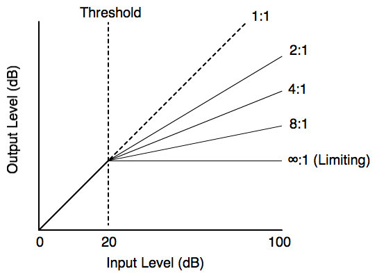
- Threshold: The audio level that the compressor begins to compress.
- Ratio: The amount of compression. For example, a 2:1 compression ratio would mean that for every 2dB of audio above the threshold, the compressor only outputs 1dB.
- Attack: The amount of time it takes for the compressor to react to the signal crossing above the threshold.
- Release: How long it takes for the compression to stop when the volume goes below the threshold.
- Output gain: Amplification to the entire signal after compression.
Many compressor pedals do not include all of these controls to simplify it’s user interaction, while professional studio compressors have many more controls such as ‘knee’, which determines how exact and sudden the change is when the signal crosses the threshold.
My design focuses on including just the controls above, but implementing them correctly.
It is important to differentiate compression and distortion. One could argue that distortion does the same thing to a signal. The difference is that distortion works instantaneously on a signal, and distorts the waveform. If you distorted a sine wave, the sine wave would be flattened out as the voltage crossed the threshold. Compressors work on a larger time window and reduce the gain of the entire signal when it crosses a threshold rather than clipping the waveform peaks.
The Circuit:
The core component of the circuit is the voltag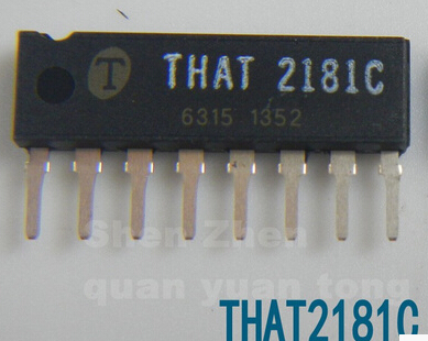 e controlled amplifier, which amplifies a signal by an amount determined by another input voltage. I chose to use the THAT 2181 VCA, which is specifically marketed for audio gain control applications, comes in an 8-pin through-hole package, but is more expensive than most ICs.Already, this IC handles the most complicated parts of the circuit. That that takes in audio directly, takes in a gain control voltage directly, changes the gain of the audio and outputs that audio.
Now the task is to generate the gain control voltage. There are many ways to implement this circuit, but I took the approach of corresponding each control to an element of the circuit. All of the controls specifically work on the control voltage, and each control is a stage that affects this signal.
I began by looking at the circuit function with no compression, where the output signal matches the input signal. This is where the ratio control setting is at 1:1.
This means the output to the VCA control input needs to set the VCA to a gain of 1. This is a set voltage that is only changed by the threshold and ratio circuits.
But where does the control voltage come from to begin with? It needs to represent the volume of the input signal, which is the parameter that is being changed.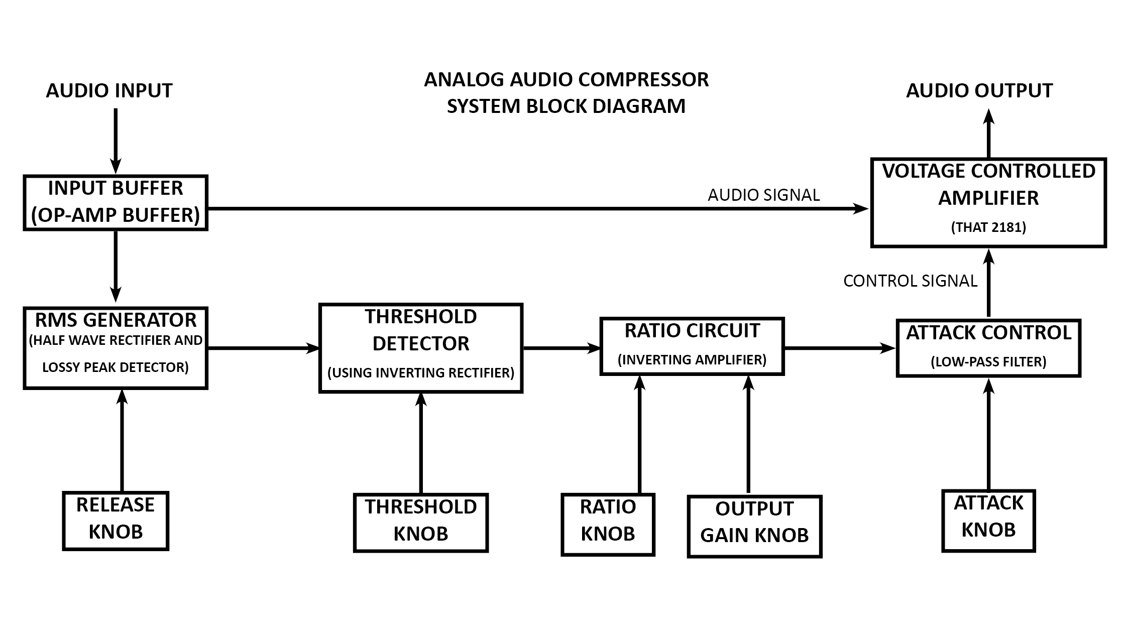
To get this signal I simply needed to create an RMS voltage of the audio. This is a changing DC voltage that represents the AC amplitude of the audio. This is implemented with a specialized version of an AC to DC converter, which is done with rectifying diodes and a filtering capacitor. I used an active half-wave rectifier and an active lossy peak detector.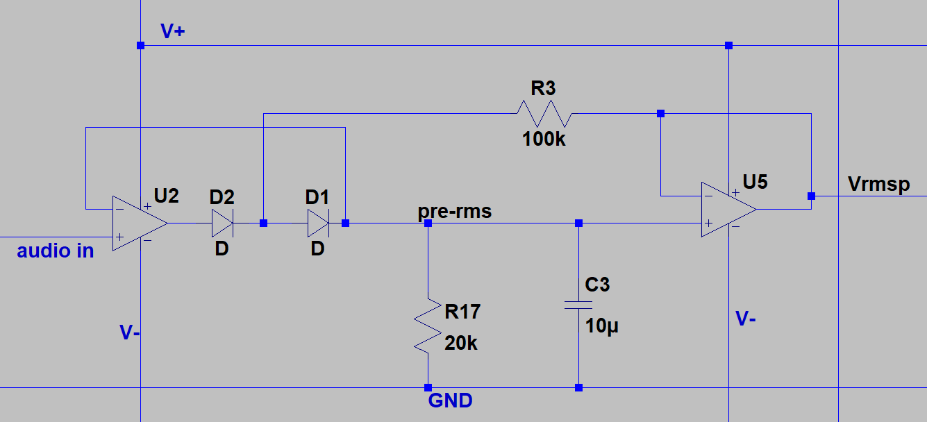
Circuit elements U2, D2, and D1 make the half-wave rectifier, which only passes positive voltages of the audio. The capacitor C3 holds the most positive voltage passed, but this voltage reduces as current drains through R17 slowly. The output voltage Vrmsp is the unfiltered RMS voltage that becomes the control signal.
The resistor R17 determines the rate at which the signal approaches zero following a peak. This resistor became a potentiometer to ground to act as the ‘release’ control, eliminating the need for a separate ‘release’ circuit element.
Now the only case where this signal is used is if it exceeds the set threshold, so the next circuit element in the chain is the threshold circuit, which is actually the most difficult to understand.
I chose to use the inverting negative control voltage pin on the VCA. This way the final control voltage will be a positive value, and the more positive it is, the more the gain is reduced. I am using inverting amplifier stages, so the control voltage switches polarity between being positive and negative after every inversion stage. There are two more amplifier stages to go before the VCA. So the RMS voltage comes out positive, then the threshold voltage needs to be negative because the ratio stage will invert it to be positive again to send to the VCA.
Unfortunately this makes the threshold circuit less intuitive because it needs to be a negative threshold, set by a negative voltage level.
The op-amp in this stage is configured as an inverting half-wave rectifier, but with a few modifications.
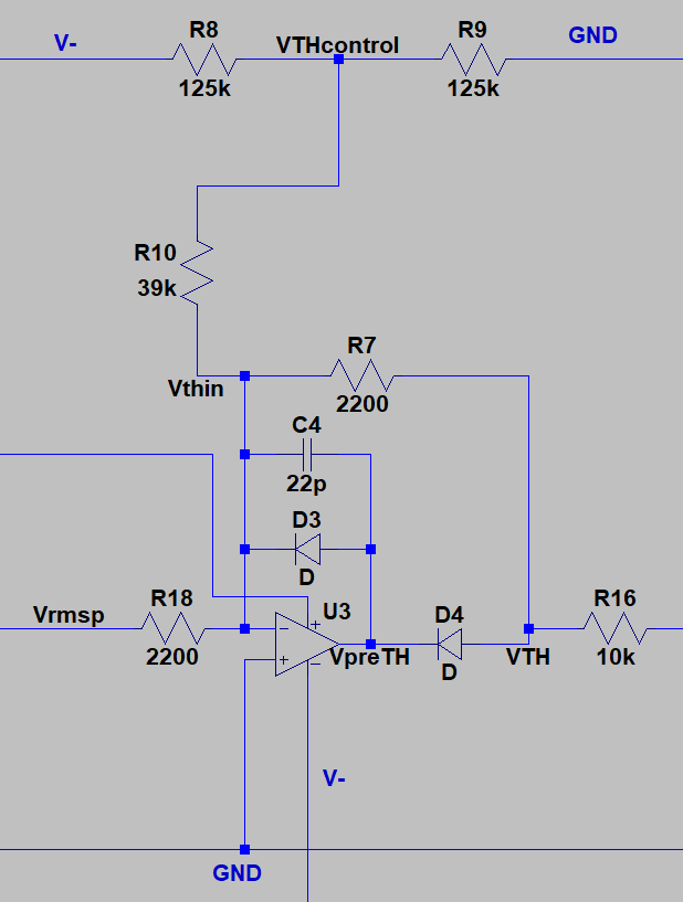
Threshold circuit
The resistors R8 and R9 are two sides of a potentiometer for the threshold knob. This sets the threshold, and also the level that must be exceeded by the input to pass information. The diodes block signal from passing unless it exceeds the voltage at VTHcontrol.
The next stage is the ratio stage. This is configured as a simple inverting op amp with adjustable gain. The ratio knob determines the fraction of the signal that will pass to the op-amp from VTH. The output gain knob is also connected to this op-amp, which adjusts the quiescent voltage level at the output of the op-amp. The control voltage is centered around this.
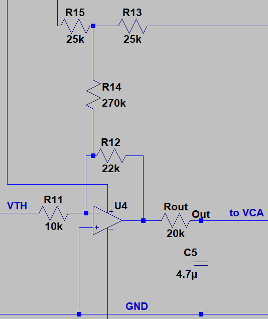
Ratio circuit
In the circuit above, R15 and R13 represent a potentiometer that controls post-gain, while R11 is a potentiometer to control the ratio.
Putting all of this together results in the automatic gain control circuit shown below.
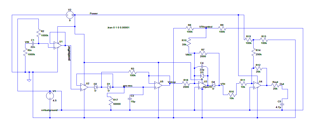
Gain Control Circuit (AGC)
The AGC circuit was simulated and adjusted in LTSpice, and then I tested the complete circuit on a breadboard to verify it’s function.
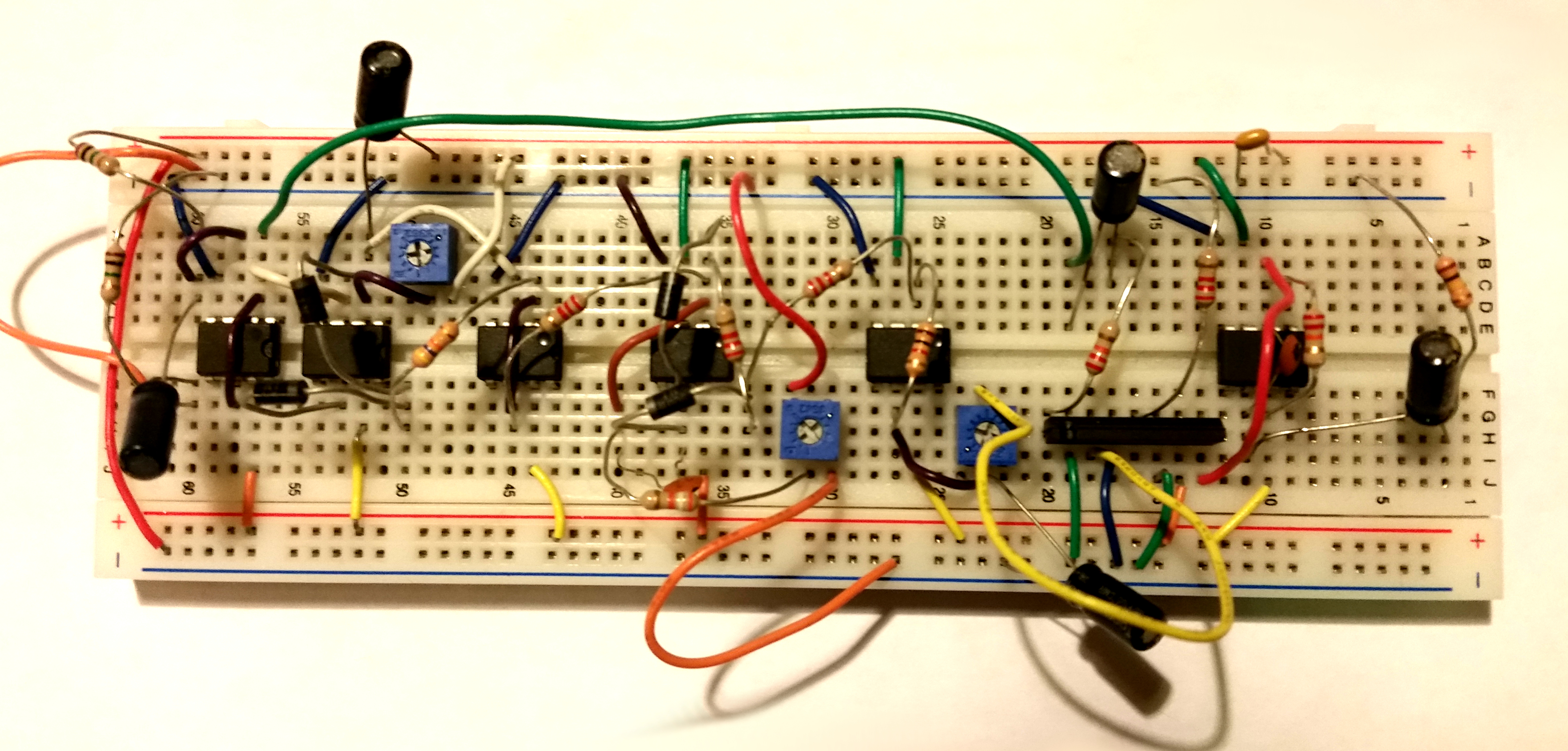
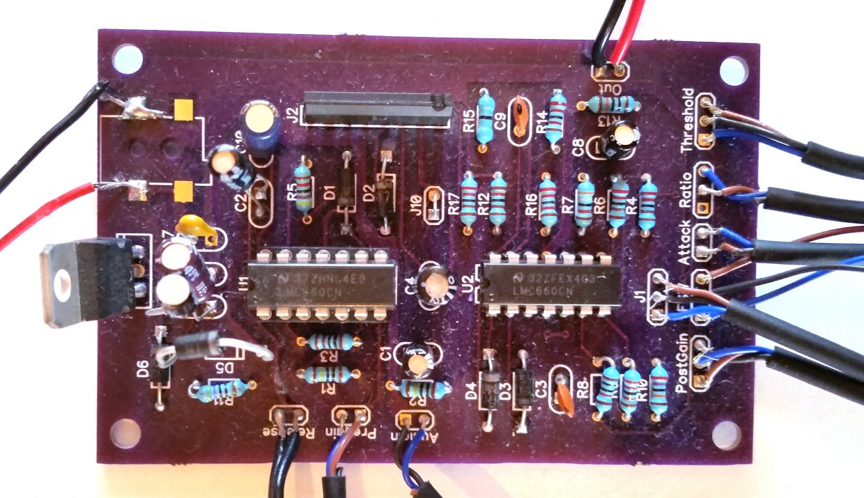
Breadboarded circuit
Finally, I added the power supply to the circuit design and completed the design and PCB layout using DipTrace. I chose an aluminum enclosure for the board and made sure the board was sized to fit this enclosure. The PCB does lack a complete ground plane, since there is a virtual ground to facilitate the audio at 4.5 volts, set by a voltage regulator off of a 9 volt supply.
The final PCB design and board received from OSHPark is shown below.
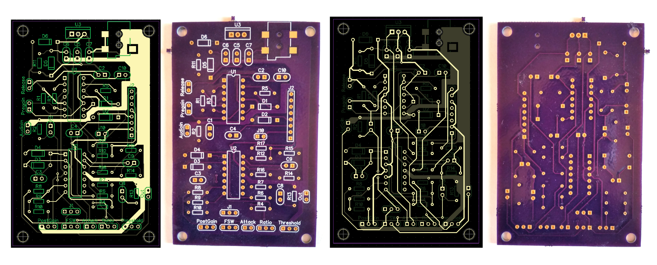
PCB
Testing:
The PCB was tested on a breadboard before sending the design out. I verfied that it functioned as expected and adjusted resistor values to make sure the controls worked for all knob positions.
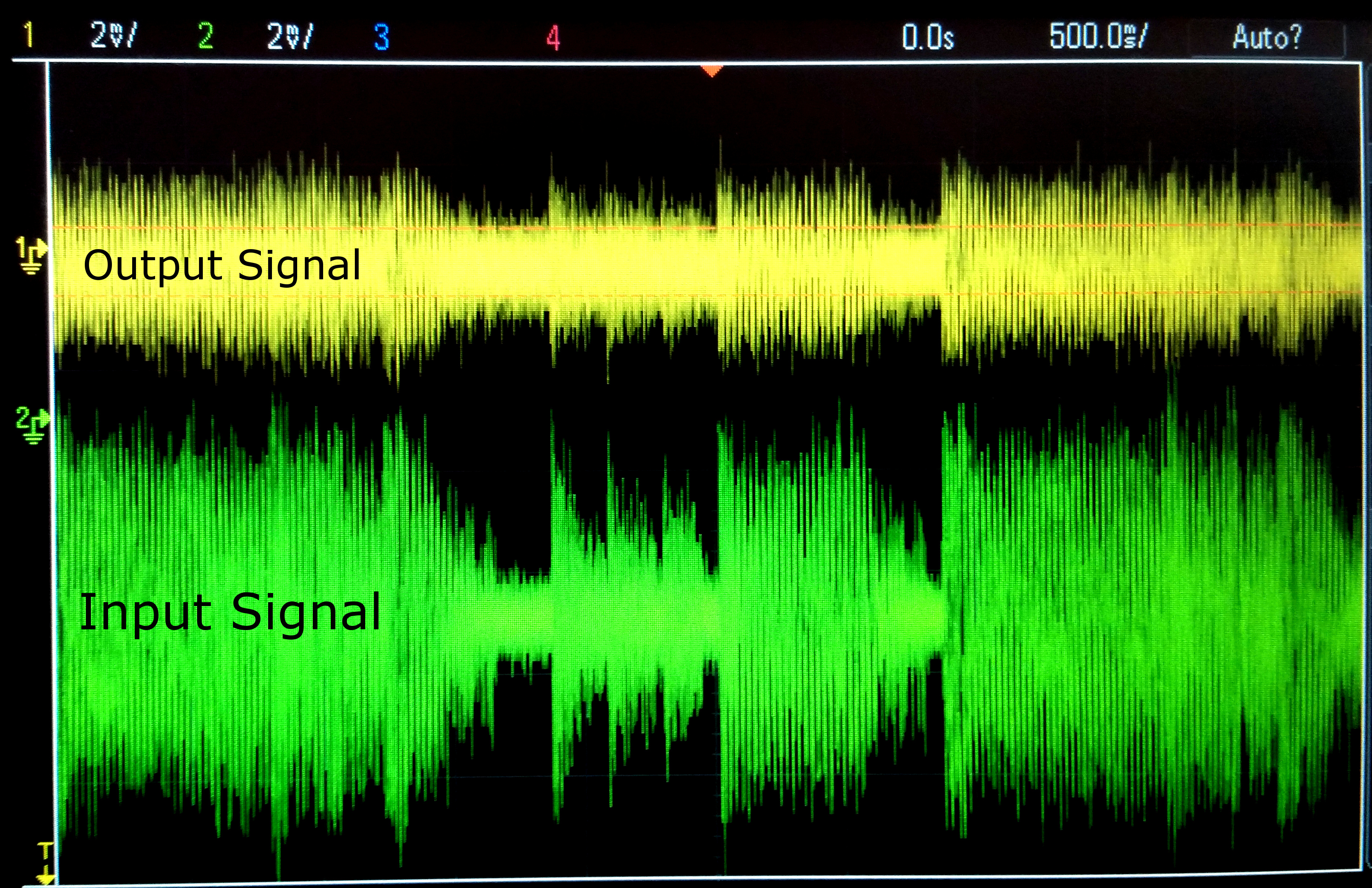
Compressed Audio in yellow
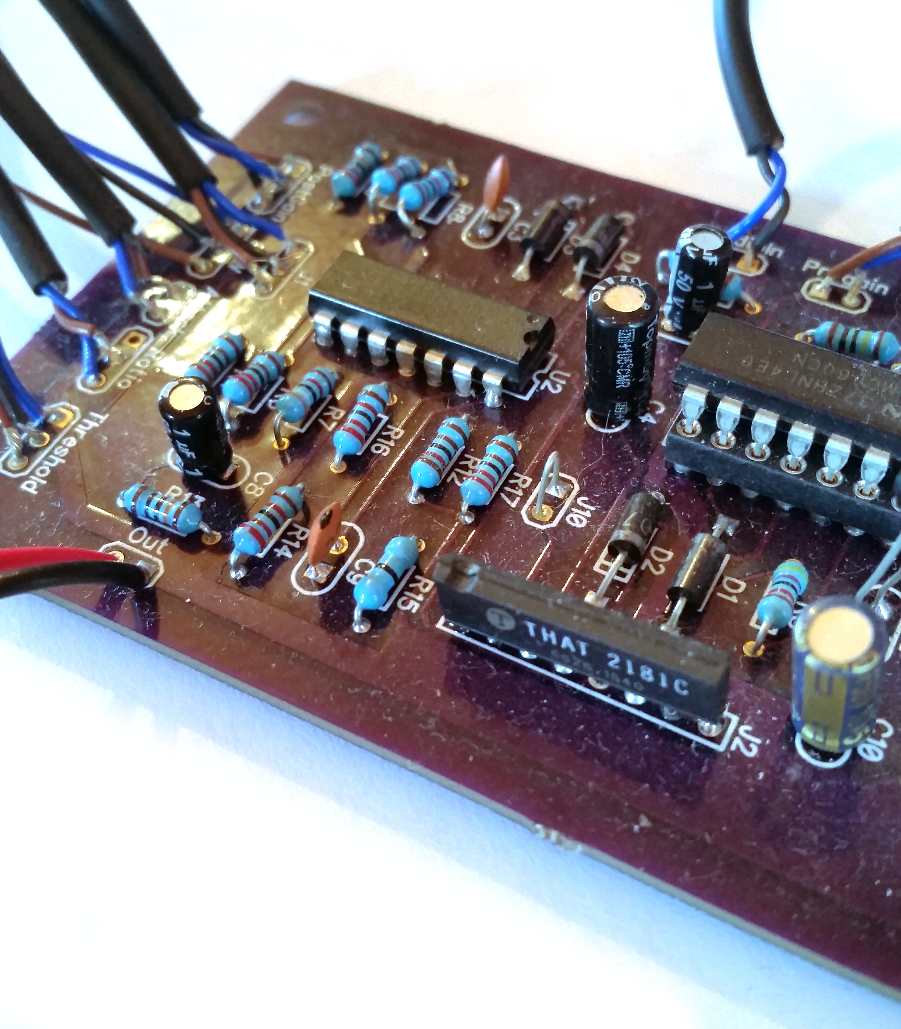
Assembly:
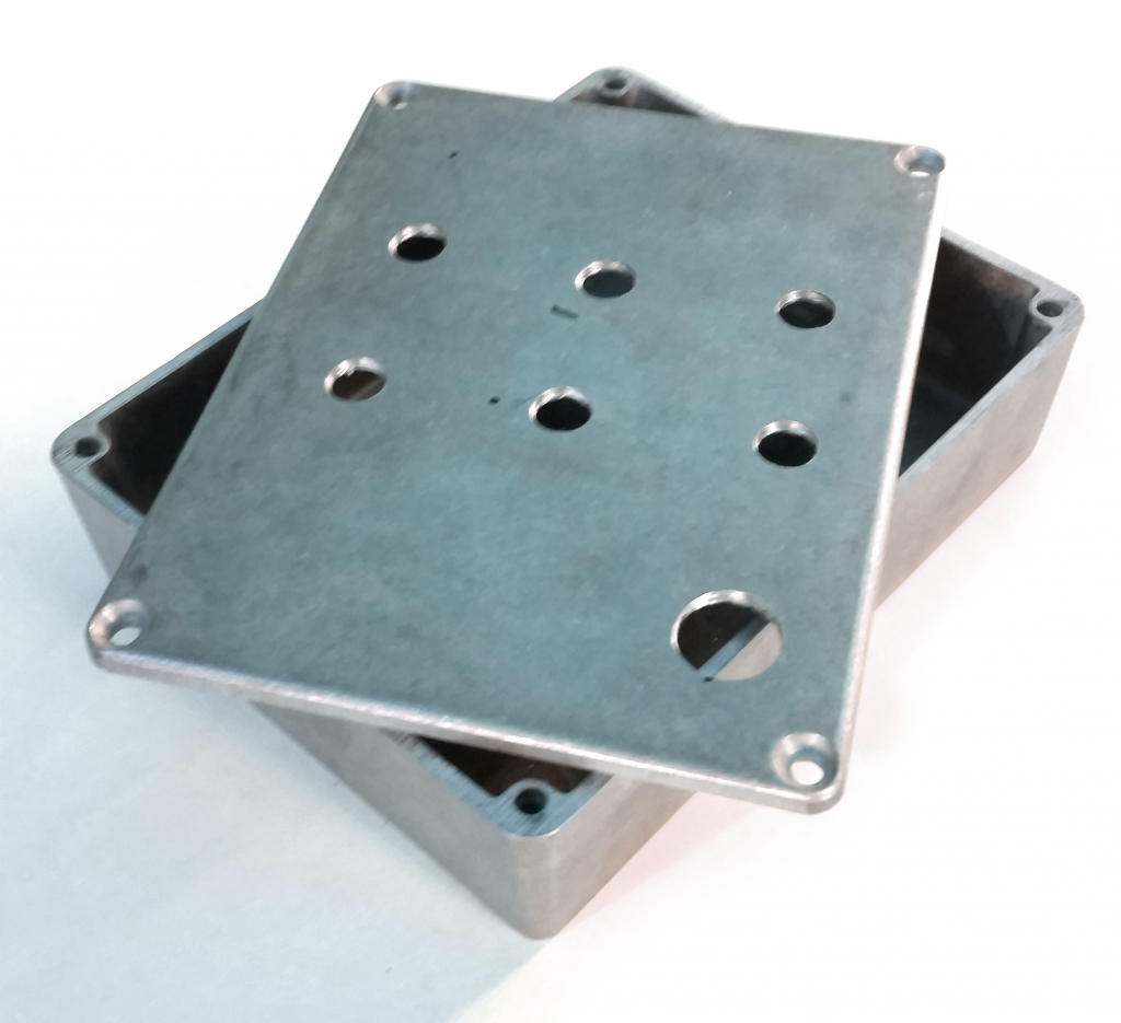
The prototype pedal enclosure
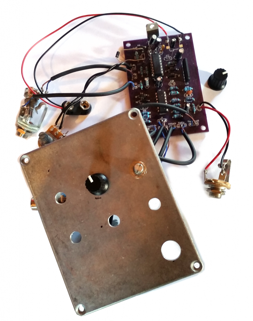
Beginning Assembly…
UX Design Considerations:
At this point I began investigating the user experience, and how to design the user interface in the most intuitive way possible. This proved challenging considering the complex nature of the device. It also became apparent that the chosen enclosure was not going to be the most ideal solution for a final product.
Traditional analog compressors usually require some sort of understanding before a musician can make the best use of them. My goal is to figure out a method of feedback that can help the user understand what the controls do…
….